
Why does this matter?
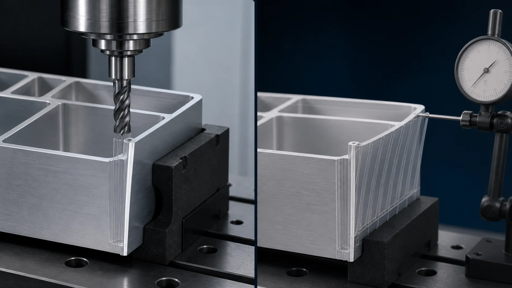
The real issue is often not whether the machine can reach the feature, but whether the part and tool remain stable while cutting it. Dimensions that look fine on paper can become difficult when rigidity is ignored.
What should you check?
- tool access and machining direction
- setup count and rigidity
- manufacturability of the geometry
- balance of cost, lead time and quality
- wall-thickness-to-span ratio
- clamping force and operation sequence
A practical evaluation sequence
For these parts, stiffness matters as much as geometry. Tool overhang, workholding, cutting force and operation order need to be considered together to avoid drift, chatter and unnecessary cycle time.
Common mistakes
- Ignoring chatter and deflection when tool reach becomes long
- Clamping a thin-wall part as if it were a rigid block
- Treating setup count only as a time calculation
Decision rule
Stable machining comes from treating geometry, tooling and workholding as one system.
What should you send for evaluation?
- available CAD, drawing or physical sample details
- critical dimensions, tolerances or fit expectations
- material and any finishing/heat-treatment requirement
- target quantity, lead-time expectation and use case
Where can Gizmak help?
We review critical surfaces, dimensions and repeatability alongside the manufacturing method and inspection plan.
Precision machining