
Why does this matter?
These details look small on a drawing, but they can change tooling, cycle time and even whether the feature is practical to machine. A few good design decisions early can avoid special tools and later revisions.
What should you check?
- critical geometry and interfaces
- nominal dimensions, tolerances and datum relationships
- fit, assembly and reference-surface expectations
- a revision-controlled CAD and drawing package
A practical evaluation sequence
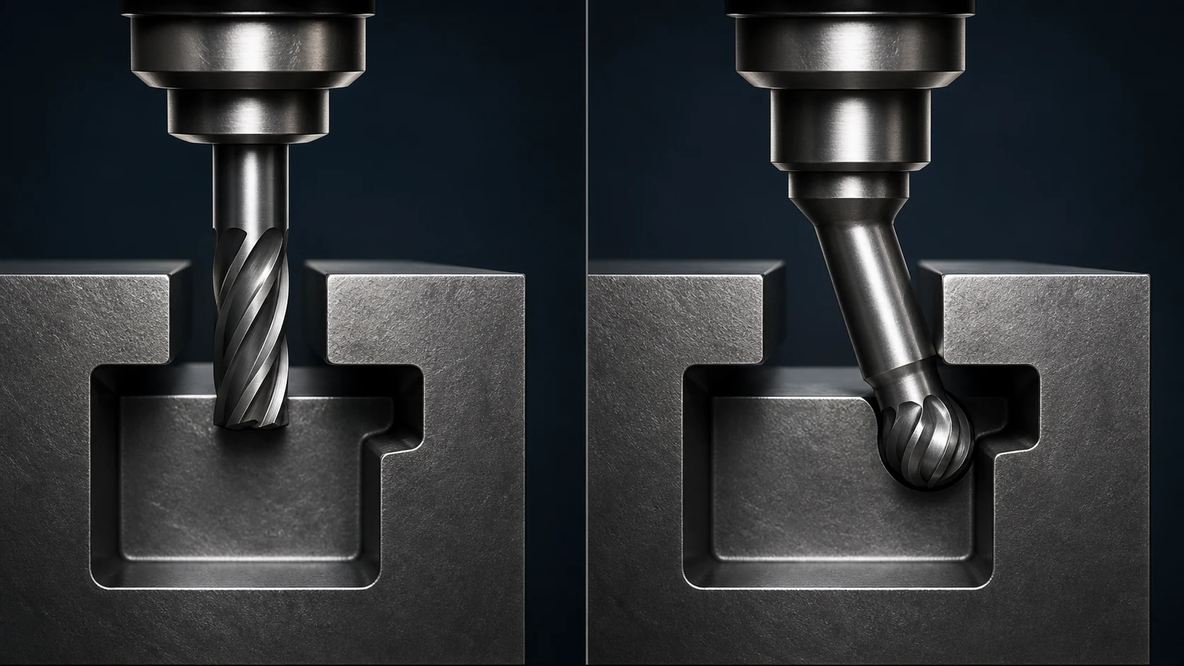
Start with what the feature actually needs to do. Before fixing a radius, hole or slot dimension, check how a tool can reach it, what cutter size is realistic and whether the depth ratio is sensible.
Common mistakes
- Assuming every CAD feature is equally easy to machine
- Treating tool access and chip evacuation as separate from part function
- Leaving features that require special tooling to be discovered during quotation
Decision rule
Define the geometry around both function and a realistic machining route.
What should you send for evaluation?
- available CAD, drawing or physical sample details
- critical dimensions, tolerances or fit expectations
- material and any finishing/heat-treatment requirement
- target quantity, lead-time expectation and use case
Where can Gizmak help?
We review critical surfaces, dimensions and repeatability alongside the manufacturing method and inspection plan.
Precision machining