
Why does this matter?
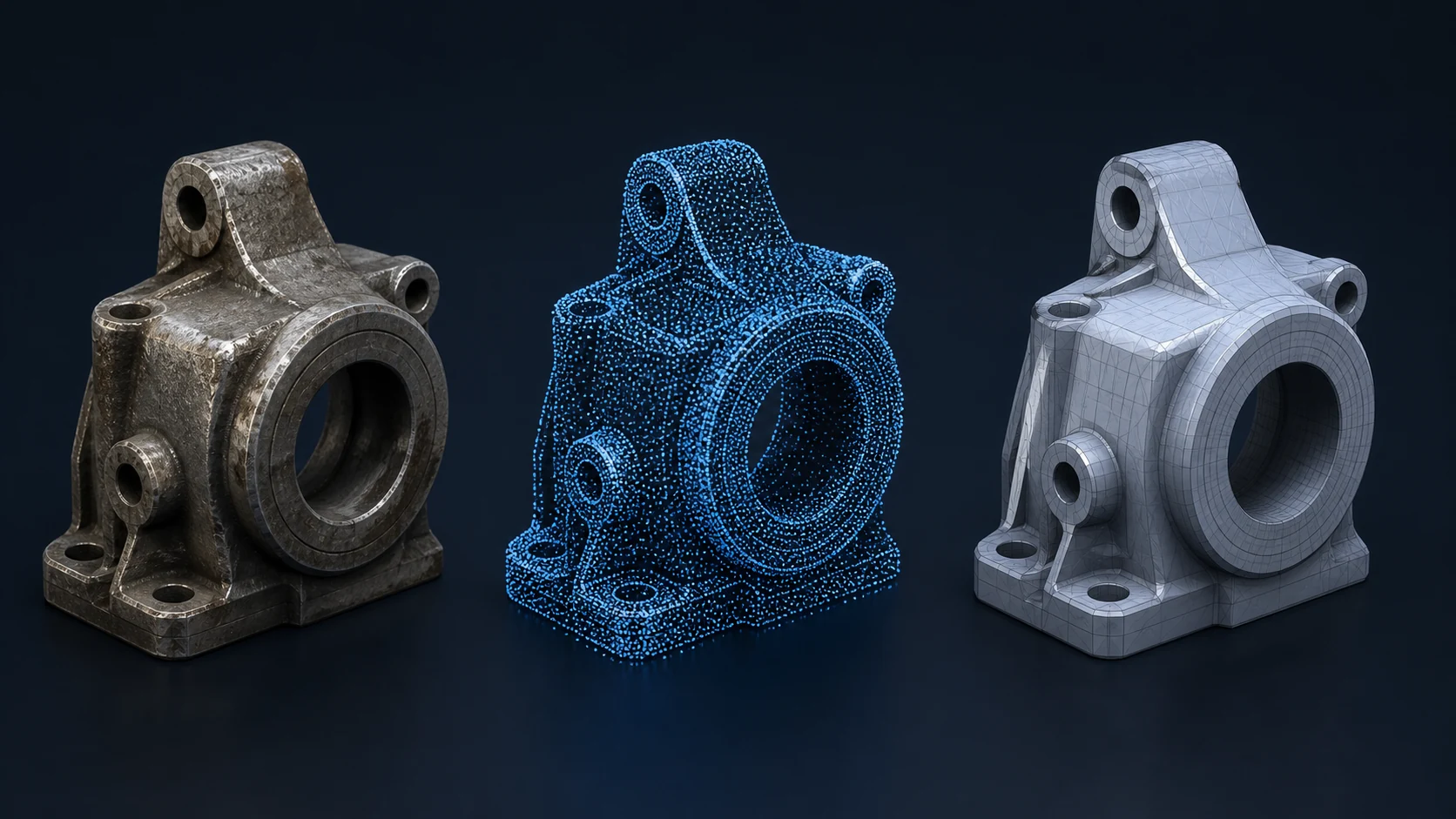
Reverse engineering is not simply copying the surface in front of you; it is recovering what the part is supposed to do. Sample condition, wear, mating parts and critical dimensions need to be considered together.
What should you check?
- Condition of the physical sample, photos and machine context
- Scan access, surface suitability and need for partner-coordinated 3D scanning
- Material, surface condition and relevant material behavior
- Critical dimensions, tolerances and required accuracy level
- 3D CAD/mesh data, revision status and required output format
A practical evaluation sequence
First decide whether scanning is actually needed. When dense free-form surface data is useful, 3D scanning can be coordinated through specialist solution partners; critical functional dimensions should still be checked against datums, conventional measurements and the manufacturing objective.
Common mistakes
- Assuming a mesh is automatically a production-ready parametric CAD model
- Treating scanner resolution and finished-part tolerance as the same thing
- Ignoring how reflective, dark, inaccessible or worn surfaces can affect captured data
3D scanning is a data-capture method; manufacturing decisions require the mesh, function, critical dimensions and CAD reconstruction to be considered together.
What should you send for evaluation?
- Condition of the physical sample, photos and machine context
- Critical dimensions, tolerances and required accuracy level
- Part function, mating components and functional relationships
- Technical drawing, datums, dimensions and available measurement results
Where can Gizmak help?
If a physical sample needs to be digitised, we can coordinate 3D scanning through specialist solution partners. The resulting data can then feed into reverse engineering, manufacturable CAD, CNC production and inspection.
Reverse engineering